Monday, July 15, 2019

Atwood RV Range for Parts?

.

My 1967 Airstream still has its original Magic Chef oven which we use at least once on every camping trip.  It has been amazingly reliable with repairs usually consisting of realigning something that vibrated out of place.  But one day I know a No-Longer-Available part will have to be replaced.  A new oven might be necessary.

The immediate problem is that no one makes an RV oven anymore – they only make ranges.  While a household wall oven would probably work, it will require 120 VAC for the electronics which may not be available depending on what type of camping going on.

Adapting modern-day RV oven parts to my half-century old oven seemed to be a reasonable avenue to investigate.  The issue here is that I have never used a modern-day, RV, gas oven to understand the differences between then-and-now operation (the Airstream’s oven has what is essentially a two-pilot light system[1] whereas modern ovens only have one).  It would be nice to play with a modern one to compare differences.

As much as we enjoy using our oven on camping trips I read that others do not apparently preferring a microwave instead.  So I was not surprised to see an RV range and hood for sale at a yard sale the other weekend.  Although it was noticeably smaller than my Magic Chef, it looked like a good “leaner” oven if the price was right.  It had obviously not been used much, and the yard-seller said it worked when removed.  Fortunately for me he was happy to mark it down to $20.

While hooking the gas up I noticed it was made by Atwood Wedgewood in 2005.


In what was no surprise, the three cook-top burners lit without incident; even the piezeo-electric sparker, a modern day feature to me, worked.  After a short line purge, the oven lit too.

While the oven was pre-heating, research on the range showed this model is still in production and sold new for around $500.  It was sold as a 17” range and has a big brother, 24” version.  Each uses the same thermostat and burner.

The Atwood’s burner is made of sheet aluminum alloy and has much less heating capacity & lower latent heat retention than the Magic Chef’s much larger cast-iron burner.


The broiler area was certainly no frills compared to my antique oven.  But, in reading camping forums, I noticed few people even know how to brown food in a gas oven.

The thermostat was found to be wildly out of calibration with no provision for adjustment.  But after bumping the temperature up and adding some stones to stabilize the heat, the oven produced a decent pan of cornbread.


The Totino’s cheese pizza cooked later came out surprisingly bad.  The lower rack position was used instead of the other, higher one which resulted in a “highly browned” bottom and uncooked top.  The top had to be broiled to make sure the cheese was melted.


It was now starting to dawn on me why some RVers did not use their ovens: the 17” version is just too small for some routine cooking tasks.  Unlike the Magic Chef, a half sheet pan will not fit.  Quarter sheet or smaller pans only.  Even with a few cooking stones, heat control is poor.  The mass of the cast iron burner in the Magic Chef coupled with the Robertshaw thermostat is tough to beat.

If push came to shove, the thermostat could be adapted but it would be a lot of work because its design made it integral to the range’s gas distribution bar.  Adapting the thermostat to flared pipe fittings would not be fun.

But keeping the limitations in mind it has been fun using the range for overflow cooking.  In fact, I made Granny Smith apple pie filling from scratch just to see how it do in the Atwood.


It turned out amazingly well and was a hit with everyone.


Cooking the pie out in my shop ended being good in an unexpected way – Per direction the glass pan was placed directly on the rack.  When it unexpectedly boiled over the syrup dripped on the metal plate dispersing the burner’s heat.  Smoke ensued in very short order and continued until a drip pan could be located/installed.

All-in-all, not counting entertainment value, a lot was learned for $20.  For now I think the range will be mounted on a stand and kept intact for overflow cooking in the summer.


Note [1]
My Overlander's '67 Magic Chef operates differently than modern ovens. Lighting the pilot light does not involve pushing & holding the knob - I just turn the knob to pilot, wait for the gas to run through, and light it.

The heat from that warms up a thermocouple hooked to the thermostat. When the thermostat calls for heat and the thermocouple is warm enough, it supplies gas to a secondary pilot immediately beside the primary pilot. This larger pilot light warms a different thermocouple hooked to a separate gas valve. When that thermocouple is warm enough, the gas valve opens and supplies gas to the main burner.

On occasion, the secondary thermocouple vibrates out of position has to be re-aligned or the main burner never lights.

Saturday, March 31, 2018

New Airstreamport for the Overlander


The master plan for keeping my 1967 Airstream Overlander at our house has always included a roof over its head.  The parking pad it sits on was sized to accommodate the standard-sized, 12’X28’ RV carport popular when the pad was poured over 10 years ago.  I even had shallow footings dug prior to the pour for extra anchoring mass.

Over the following years the subject was occasionally pursued only to find no professionals interested in adapting an “off-the-shelf” carport to fit on the pad’s irregularly-sloped surface.  One day I woke and decided it was just time to get it done even if it meant doing it myself.  Not that that the task intimidated me - I was just surprised I could not throw too much money at something to get it done.

After locating a supplier, a deposit was placed on a 12’X30’X12’ (latest standard size) Eagle Carport.  Around two weeks later a dually with a really nice flatbed trailer backed up with the new, unassembled Airstreamport.


Two guys got out and worked together like a well-oiled machine assembling the Overlander’s new roof on a relatively flat section of land & concrete.


Wedge anchors were used to hold the front half of the structure to concrete while rebar spikes took care of the part over dirt.


The guys finished up in about three hours.  They did a super job, and I have zero complaints about either the building or their workmanship.


So although now the Airstream had a roof over its head, the tires were sitting on dirt, and the pad’s full hookups, which hook up to the back of the Airstream, were at the side.


Thought was given to relocating the hookups and pouring additional concrete.  Parking would be greatly simplified.  But I did not want a backyard full of concrete when the pad was poured, and the sentiment had not changed.  The airstreamport would have to be relocated to the front of the pad once suitable supports were made.

After deciding to place a support under every stud that would not be on flat land, the studs’ locations were marked on a “storypole”.  Of note, the locations varied greatly between both each other, and side-to-side.


After leveling the storypole, the studs’ locations were projected onto the concrete.  Using a hardboard template a triad of holes were started with a small hammer drill.


A big hammer drill was used for the actual anchors since ½-inch diameter holes at least 2-3/4 inches deep were needed.


There was a delay in getting the ¼-inch steel plate sheared for the actual mounting plates.  To keep the project going, hardboard mockup plates were made to locate the all-thread studs in the holes prior to anchoring.


The Internet appears to be comfortable with the use of anchoring adhesive when used according to the directions.  There did not appear to be a brand preference.  The Sika brand was chosen simply because it came with two nozzles.


As luck would have it, there was enough adhesive left to anchor my drill press to the shop floor.  I am the only homeowner I know that has done this!


After allowing the adhesive to cure, the storypole was brought back out to determine the supports’ heights.


Fortunately, my metal cutoff saw had just been fitted with a new wheel.  It was certainly needed for the 2-1/2 inch tube stock.


Between hardboard mounting plates & top tabs, and the real, metal supports, there was high confidence that the actual end-product was going to work as intended.


In time the mounting plates got sheared (thanks Kenny!).  Drilling the ½-inch diameter holes went well with the drill press securely mounted to the floor.


One of the steel plates was then placed on an all-thread triad for a quick sanity check – all was well.


My Lincoln stick-welder is conveniently located right by both my toolbox and big door, and is ready to weld in seconds.  But since I wanted this job to look good, it never moved and my buddy Heath MIG welded the supports for me.  He did an outstanding job.


Rustoleum cold galvanizing spray paint was used as a top coat.


As expected, the supports bolted up beautifully.


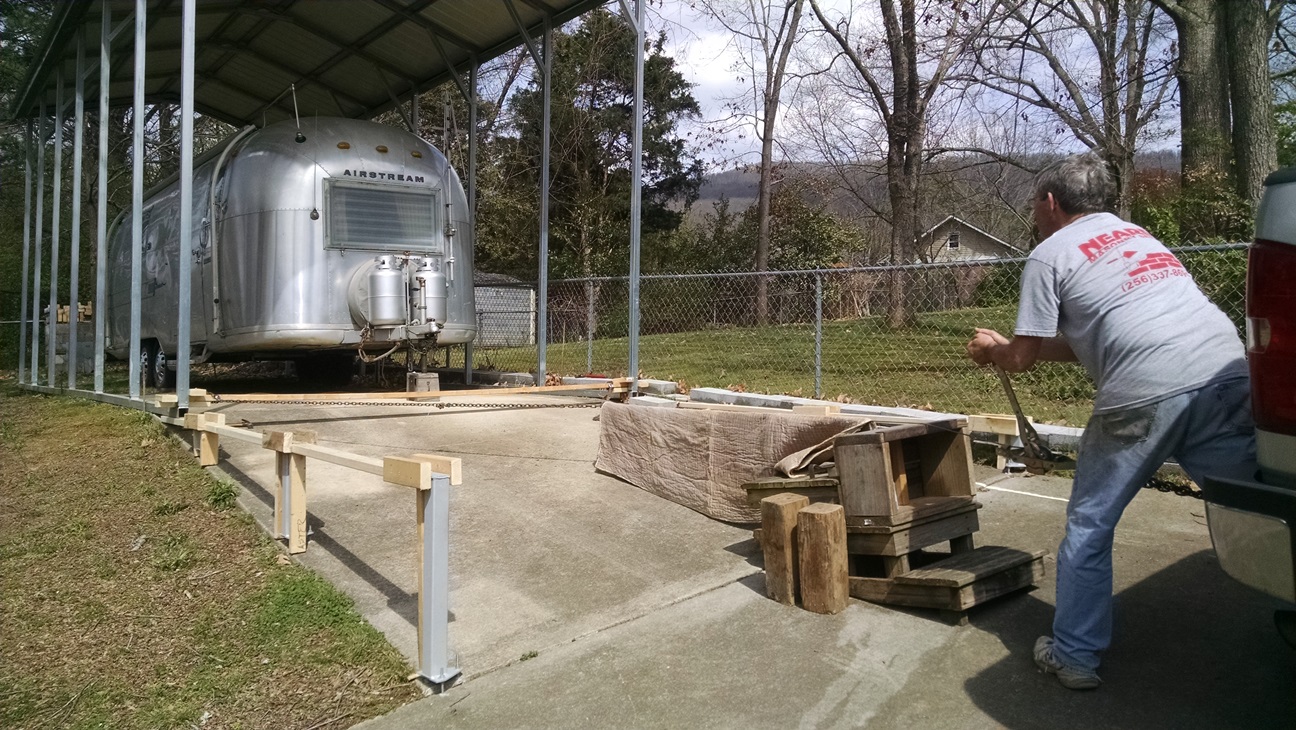
The next step was to move the carport forward to its new digs.  The easiest & fastest option would have been to invite a bunch of guys over for barbeque & beer.  Afterwards we could all stagger over and brute force the thing in place.  But since most of my friends are now middle-aged there was a good chance someone would get hurt.  So I went with Plan B – a come-along winch.

In preparation, 2X4s were sized to act as tracks & track supports between each support.


After checking the weather forecast to make sure it was not projected to be windy, the existing anchor bolts were Sawzalled off and the rebar spikes crowbarred up.


After that it was simply a matter of slowly winching the Airstreamport forward to its new location.


Although I did get my wife to come out and help me keep an eye out for potential problems during the move, I really didn’t want anyone else involved.  But of course the neighbors had to come watch over the fence.  Fortunately nothing went wrong, and the move was completed in less than ½ an hour.


After removing the wood cribbing, the airstreamport was then nut & bolted to the new supports, wedged anchored to the concrete or rebar-spiked to the ground as required.  After a little touch-up painting on everything, I was pleased with how it turned out.


The Airstream’s tires had really gotten muddy during their brief time in yard.  Pulling it forward for a wash-off gave me a better opportunity to sweep up construction debris.


One of the neighbors who watched the effort later independently volunteered that he thought the completed project turned out nicely.  I have to agree.


Update:
My wife & I enjoy yardsales, and around four years ago I was fortunate to acquire two very nice, new, digital-ready outdoor TV antennas for a dollar (the entire tale is at this link).  The best one was mounted on the house's chimney as part of our severe weather reactance plan should the cable go out.  While the other antenna was offered to others, no one one took me up on the freebie.

Severe Weather Plan C is to retreat to the Overlander since it has its own antenna.  But I noticed the new Airstreamport, with all its metal, might interfere with the signal.  So the other antenna was mounted on a mast attached to the new structure.  14 channels - Nice!


.

Thursday, October 26, 2017

Granny’s Clock Revisited


Around a year ago, I wrote about the difficulties of getting my family heirloom clock running again.  In concluding the post, the hope was expressed that my clock toolbox would not come out again any time soon for this project.  Sadly, the clock only ran for a few weeks before the time-side mainspring broke.


To add to my frustration, it broke with such force that it fractured one of the clock face supports.

Since it was essentially a new movement, I decided the failure was due to a bad spring.  Instead of repairing this movement it was swapped with the first replacement movement (click here to read the original tale) as that movement had already been repaired, and was simply sitting in a box waiting to run again.

Maddeningly, that movement only kept time for a few weeks before its time-side mainspring broke.  In frustration, I walked away from the clock for several months.

After reviewing several options, I decided the best course of action was to replace both springs with high-quality versions made in Germany.  Doing this requires disassembling the movement.

The first step in getting the movement apart is to contain the springs’ energy so they do not continue to run the movement or, in the case of the broken spring, press on other gear arbors.  To do this, the springs are wound up tight & fitted with special C-rings to keep them wound.  But between one spring being broken, and there being no plans to reuse the other one, hose clamps worked better for the effort.


The time-side spring was found to be broken about 2-1/2 turns out from the center.


New springs come tightly wrapped & held together with baling wire.  As such, the springs cannot be mounted in a mainspring winder to have the wire removed.  I find holding the spring flat against the table with leather gloves with the wire is removed works well to get it safely opened.


Although relatively clean, the springs come dry, and must be lubed before use.


I have an Ollie Baker mainspring winder which makes easy work of mounting springs on arbors.


For reassembling a clock, the C-rings mentioned earlier work are easier to remove from the assembled movement than hose clamps.


I always have to remember to place the C-ring closer to the gear so that the spring will fit inside to limiting pegs inside the movement.


Reassembly of the movement went better than usual because a new, special-purpose tool was purchased to help nudge all the all the arbors into position.  It worked much better than the slender screwdriver I used to use.


After synching the strike side, the movement was once again mounted in a temporary frame and allowed to run for a couple of weeks.  The new springs performed better than the old ones because the clock appeared to keep more even time than before.

The opportunity was taken to relocate the clock to between the two smaller clocks.  It certainly looks better being centered.


I have high confidence in this repair.  But, we’ll see!


.

Thursday, March 23, 2017

Whistle and Bell for the T&K Railway


In an effort to add realism to my O-gauge ceiling train loop, I recently completed both an Arduino-controlled, servo project to modulate the airflow to an eight-chime whistle made of one-inch PVC pipes, and a full-size crossing bell.

For the whistle assembly, various-length pipes were mounted in a piece of wood cut to match the inside diameter of a one-gallon windshield washer fluid container.  Afterwards the assembly was painted with bronze-colored spray paint.


A lanyard attached to a retractable key chain modified to include a potentiometer is pulled to signal the Arduino.  The length of pull modulates the amount of air delivered to the whistle manifold.  Although my preference is for something prettier than what I built, the few store-bought encoders suitable for the effort were awfully expensive.


The Servo-controlled air valve took the most effort because I had to design and fabricate the valve itself.

Air power for the project is supplied by the motor from a vacuum cleaner found on the side of the road.  A new enclosure had to be constructed because the original one had no way to connect the hose to the outlet side of the fan.  Wood was chosen in an effort to dampen the noise of the device’s universal motor.


Although not obvious, the air valve is mounted inside the enclosure to modulate the amount of air leaving through the hose.

Even with the thick-walled box, the blower is still loud.  As a consequence it was subsequently mounted to a floor joist underneath the house.

Although the setup worked exactly as expected, a problem popped up after only a minute or two of operation – sluggish or no valve operation.  It seems the blower produces an unanticipated amount of heat while in operation.  If the air valve is not allowing air to pass, this heat builds up in the enclosure.  The plastic parts of the valve apparently did not like the excess heat.  Fortunately, everything worked okay after being allowed to cool.

The solution ended up being easy – a blower control relay, mounted in a blue electrical box, was wired to one of the Arduino’s digital out ports.  The code was modified to turn the relay on only when the lanyard is pulled.


Although my camera does not do the new project justice, here’s the 8 chime whistle compared to the train’s whistle.

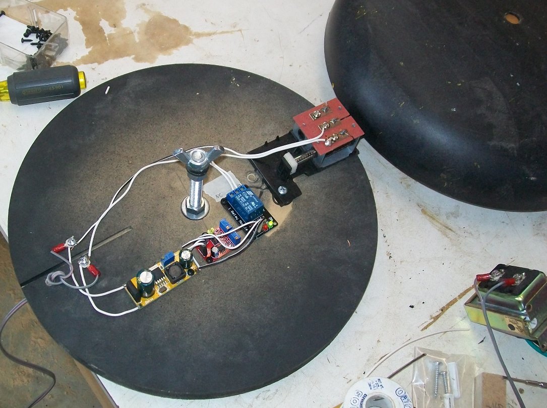
My adaptation of a crossing bell, while technologically simpler than the whistle, had a higher parts count.  The striker is one hammer out of a doorbell ringer.  Oddly, the big box store sold me a doorbell ringer kit which involved the doorbell, two switches, and a 16 VAC transformer for just $13.  The price struck me odd because they were selling the transformer by itself for $14.  Go figure.

The control circuit is an NE555 timer hooked up to the transformer through an LM2596 adjustable power supply to a relay which actuates the modified doorbell ringer.


Here’s a checkout demo before the bell was installed:  Crossing bell.

The assembly was mounted on the wall behind the door to the room.  Even with a rubber-tipped hammer, it is still fairly loud.


For now I flip a toggle switch to turn on the bell.  Although I have an IR detector in my toy-box which could be used as a traffic detector, the jury is still out on the best way to implement the bell.

I’ll keep you posted.


.

Thursday, January 19, 2017

Re-sealing the 1967 Airstream Bay Breeze AC


Back in the sixties, RV air conditioners had an inside unit & outside unit with the two connected by a 3-inch service hole.  Nowadays, RV ACs are comprised soley of a top unit which sits on a 14-inch square hole.

My 50 year-old travel trailer developed a leak which I finally decided could only be resolved by removing the top portion.  The tale can be followed at this link on my Airstream's web page.