Thursday, October 26, 2017

Granny’s Clock Revisited


Around a year ago, I wrote about the difficulties of getting my family heirloom clock running again.  In concluding the post, the hope was expressed that my clock toolbox would not come out again any time soon for this project.  Sadly, the clock only ran for a few weeks before the time-side mainspring broke.


To add to my frustration, it broke with such force that it fractured one of the clock face supports.

Since it was essentially a new movement, I decided the failure was due to a bad spring.  Instead of repairing this movement it was swapped with the first replacement movement (click here to read the original tale) as that movement had already been repaired, and was simply sitting in a box waiting to run again.

Maddeningly, that movement only kept time for a few weeks before its time-side mainspring broke.  In frustration, I walked away from the clock for several months.

After reviewing several options, I decided the best course of action was to replace both springs with high-quality versions made in Germany.  Doing this requires disassembling the movement.

The first step in getting the movement apart is to contain the springs’ energy so they do not continue to run the movement or, in the case of the broken spring, press on other gear arbors.  To do this, the springs are wound up tight & fitted with special C-rings to keep them wound.  But between one spring being broken, and there being no plans to reuse the other one, hose clamps worked better for the effort.


The time-side spring was found to be broken about 2-1/2 turns out from the center.


New springs come tightly wrapped & held together with baling wire.  As such, the springs cannot be mounted in a mainspring winder to have the wire removed.  I find holding the spring flat against the table with leather gloves with the wire is removed works well to get it safely opened.


Although relatively clean, the springs come dry, and must be lubed before use.


I have an Ollie Baker mainspring winder which makes easy work of mounting springs on arbors.


For reassembling a clock, the C-rings mentioned earlier work are easier to remove from the assembled movement than hose clamps.


I always have to remember to place the C-ring closer to the gear so that the spring will fit inside to limiting pegs inside the movement.


Reassembly of the movement went better than usual because a new, special-purpose tool was purchased to help nudge all the all the arbors into position.  It worked much better than the slender screwdriver I used to use.


After synching the strike side, the movement was once again mounted in a temporary frame and allowed to run for a couple of weeks.  The new springs performed better than the old ones because the clock appeared to keep more even time than before.

The opportunity was taken to relocate the clock to between the two smaller clocks.  It certainly looks better being centered.


I have high confidence in this repair.  But, we’ll see!


.

Thursday, March 23, 2017

Whistle and Bell for the T&K Railway


In an effort to add realism to my O-gauge ceiling train loop, I recently completed both an Arduino-controlled, servo project to modulate the airflow to an eight-chime whistle made of one-inch PVC pipes, and a full-size crossing bell.

For the whistle assembly, various-length pipes were mounted in a piece of wood cut to match the inside diameter of a one-gallon windshield washer fluid container.  Afterwards the assembly was painted with bronze-colored spray paint.


A lanyard attached to a retractable key chain modified to include a potentiometer is pulled to signal the Arduino.  The length of pull modulates the amount of air delivered to the whistle manifold.  Although my preference is for something prettier than what I built, the few store-bought encoders suitable for the effort were awfully expensive.


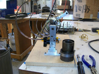
The Servo-controlled air valve took the most effort because I had to design and fabricate the valve itself.

Air power for the project is supplied by the motor from a vacuum cleaner found on the side of the road.  A new enclosure had to be constructed because the original one had no way to connect the hose to the outlet side of the fan.  Wood was chosen in an effort to dampen the noise of the device’s universal motor.


Although not obvious, the air valve is mounted inside the enclosure to modulate the amount of air leaving through the hose.

Even with the thick-walled box, the blower is still loud.  As a consequence it was subsequently mounted to a floor joist underneath the house.

Although the setup worked exactly as expected, a problem popped up after only a minute or two of operation – sluggish or no valve operation.  It seems the blower produces an unanticipated amount of heat while in operation.  If the air valve is not allowing air to pass, this heat builds up in the enclosure.  The plastic parts of the valve apparently did not like the excess heat.  Fortunately, everything worked okay after being allowed to cool.

The solution ended up being easy – a blower control relay, mounted in a blue electrical box, was wired to one of the Arduino’s digital out ports.  The code was modified to turn the relay on only when the lanyard is pulled.


Although my camera does not do the new project justice, here’s the 8 chime whistle compared to the train’s whistle.

My adaptation of a crossing bell, while technologically simpler than the whistle, had a higher parts count.  The striker is one hammer out of a doorbell ringer.  Oddly, the big box store sold me a doorbell ringer kit which involved the doorbell, two switches, and a 16 VAC transformer for just $13.  The price struck me odd because they were selling the transformer by itself for $14.  Go figure.

The control circuit is an NE555 timer hooked up to the transformer through an LM2596 adjustable power supply to a relay which actuates the modified doorbell ringer.


Here’s a checkout demo before the bell was installed:  Crossing bell.

The assembly was mounted on the wall behind the door to the room.  Even with a rubber-tipped hammer, it is still fairly loud.


For now I flip a toggle switch to turn on the bell.  Although I have an IR detector in my toy-box which could be used as a traffic detector, the jury is still out on the best way to implement the bell.

I’ll keep you posted.


.

Thursday, January 19, 2017

Re-sealing the 1967 Airstream Bay Breeze AC


Back in the sixties, RV air conditioners had an inside unit & outside unit with the two connected by a 3-inch service hole.  Nowadays, RV ACs are comprised soley of a top unit which sits on a 14-inch square hole.

My 50 year-old travel trailer developed a leak which I finally decided could only be resolved by removing the top portion.  The tale can be followed at this link on my Airstream's web page.